Rigid Flex Circuits for High-Frequency Applications
Rigid Flex Circuits for High-Frequency
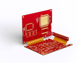
A rigid flex circuit is a hybrid of rigid and flexible PCBs that incorporates rigid and flex components in the same panel. This gives the design dynamic adaptability and stability, allowing for a wider range of circuit routing densities than typical rigid boards. Rigid-flex boards also offer the benefit of lowering component costs and simplifying assembly.
The process of fabricating a rigid-flex circuit begins with a single or double-sided, adhesiveless copper clad flex board. The flex may be made from pre-laminated FR-4 or a roll of unclad copper film. The flex board is then laminated to the rigid panels using an appropriate bonding agent. This is followed by drilling, etching and plating. The final product is a plated through-hole (PTH) rigid flex board with rigid edges and borders to frame the flex sections.
rigid flex circuits can be used for a wide range of applications, from medical imaging equipment to military missile guidance systems and wearable electronics. They can withstand high levels of shock, vibration and are very robust. These benefits make them particularly suited for use in harsh environments where the device must work under demanding conditions.
Rigid Flex Circuits for High-Frequency Applications
Compared to alternative interconnect solutions, such as solder joints or contact crimps, rigid-flex circuits can save space and reduce the number of points where failures could occur. The reduced number of points also allows the product to be designed into smaller and lighter packaging.
The underlying layer of copper on rigid flex circuits can be either a thin, adhesiveless foil or a thicker, soldered, copper-clad surface. The latter is often preferred for high-frequency applications because of the greater conductivity offered by the thicker surface. A thicker copper surface is also more durable in a hostile environment.
As the copper is deposited, it is exposed through a photosensitive etch resist mask pattern. This is then chemically stripped, exposing the required pads and via patterns for the manufacturing process. The holes are drilled mechanically with precision drilling systems, enabling the electrical connections to be established between the flex and rigid sections.
When the holes are plated, they can be covered with a variety of finishes, including tin and soft gold. These coatings can protect the copper during assembly and reflow soldering, as well as reduce the risk of accidental contact between bare and plated surfaces.
Once the flex is etched and plated, it is ready for lamination to the rigid sections. Typically, two flex layers are inserted between three rigid sections of the same thickness. The resulting rigid-flex circuit is plated and etched, with the flex layer edges being trimmed, cut and blanked to allow for a border for stiffeners.
The most important step in designing a rigid-flex circuit is finding the right manufacturer to work with. The ideal partner will have a proven track record of working with customers on projects of all sizes and can demonstrate that they offer a high level of quality, reliability and customer support. This will allow you to create electronic devices with confidence that are both cutting-edge and reliable.